In a diagram, an edge is a directed relation between two nodes. The word "directed" indicates that the direction in which the relation is used is relevant for the diagram.
An edge is normally depicted by an arrow between two nodes. The arrow points to the "to" node. It can also be represented by means of boxing and boxed nodes, in which one node contains the other.
In Collibra, you can:
- Add an edge to a node.
- Edit an edge.
- Remove an edge of a node.
Add an edge to a node
- Open the diagram view.
- Click
 .
.
The General properties form appears. - Select a node in the diagram.
The Node properties form appears. - In the Node properties form, go to the Edges section.
- Do one of the following:
- Under Outgoing, click Add.
This adds an edge starting from the selected node. - Under Incoming, click Add.
This adds an edge ending in the selected node.
- Under Outgoing, click Add.
- Define the edge characteristics:
Edge characteristic Description Relation Type
Choose a relation type from the list of applicable types.
Start typing to reduce the list.Role direction
Choose in which direction to traverse a relation.
For example, [Business asset] groups/is grouped by [Business Asset], if you select the Role direction option, you traverse in the role direction, meaning from parent to child. If you don't select this option, you traverse in the co-role direction, meaning from child to parent.To
Choose the type of node (asset or complex relation) from the list of types. The drop-down list first shows node types that match the relation type, but also allows you to choose a node whose type does not match the relation type. You can select a new node or a node that already exists on the diagram.
Style
Style of the edge.
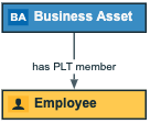
- Arrow: An arrow from the outgoing side to the incoming side. The pointer is on the incoming side of the arrow. This is the default setting.Example
Business Asset is the selected node.
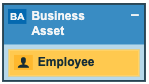
- Boxed: The node on the outgoing side is enclosed by the node on the incoming side.Example
Business Asset is the selected node. It is boxed by Employee.
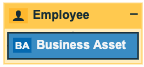
- Boxing: The node on the outgoing side encloses the node on the incoming side.Example
Business Asset is the selected node. It is boxing Employee.
- Arrow: An arrow from the outgoing side to the incoming side. The pointer is on the incoming side of the arrow. This is the default setting.
- Click Add.
- Optionally, edit the edge.
Tip This allows you to edit the label of the edge.
- Above the diagram, to the right, click Save.
Edit an edge
- Open the diagram view.
- Click .
The General properties form appears. - Do one of the following:
- Select an edge in the diagram.
- Select a node in the diagram and click
 next to an incoming or outgoing edge in the edge section.
- Enter the required information.Show me the properties.
Field Description Relation Type Relation type of the currently selected edge.
The drop-down list shows all available directed relation types.
Role direction Indicates the direction in which instances of this relation type are traversed.
- If the checkbox is selected: The edge is traversed from head to tail. The edge label is the role of the relation type.
- If the checkbox is cleared: The edge is traversed from tail to head. The edge label is the co-role of the relation type.
From Node from which the edge starts.
In the drop-down list of nodes, the nodes that match the current type of edge are shown first (under Matching types). Nodes that don't match the current type are shown after the matching types (under All types). It is also indicated if the node is already in the diagram (on diagram).
A matching node is (a parent of) the head asset type of the current relation type (if Role direction is selected) or (a parent of) the tail asset type of the relation type (if Role direction is cleared).
Selecting a node that is already in the diagram view adds this edge to that node.
Selecting a node that is not yet in the diagram view adds this node to the view.
To Node in which the edge ends.
You must select an ID from the drop-down list of nodes. The list contains nodes that match the current type of edge.
A matching node is (a parent of) the tail asset type of the current relation type (if Role direction is selected) or (a parent of) the head asset type of the relation type (if Role direction is cleared).
Selecting a node that is already in the diagram view adds this edge to that node.
Selecting a node that is not yet in the diagram view adds this node to the view.
Style Style of the edge.
- Arrow: An arrow from the outgoing side to the incoming side. The pointer is on the incoming side of the arrow. This is the default setting.Example
Business Asset is the selected node.
- Boxed: The node on the outgoing side is enclosed by the node on the incoming side.Example
Business Asset is the selected node. It is boxed by Employee.
- Boxing: The node on the outgoing side encloses the node on the incoming side.Example
Business Asset is the selected node. It is boxing Employee.
Label Label for the edge.
If you don't specify a label, either the role name or the co-role name of the relation type from the operating model is used in both the diagram view and the diagram.
If the Role direction check box is selected, the label is the role of the relation. If it is cleared, the co-role is used.
- Above the diagram, to the right, click Save.
Remove an edge of a node
- Open the diagram view.
- Click .
The General properties form appears. - Select a node in the diagram.
The Node properties form appears. - Do one of the following:
- Click
 next to an incoming or outgoing edge in the edge section.
 - Select an edge in the diagram and click in the upper right corner.
- Click
- Above the diagram, to the right, click Save.