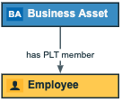
Note The images in this topic show the old diagram user interface. You can still refer to them to understand the concept.
The Edge Properties section is used to define edges in the diagram view. This section appears when you edit a diagram view and select an edge.
| Field | Description |
|---|---|
| Relation Type |
Relation type of the currently selected edge. The drop-down list shows all available directed relation types. |
| Role direction |
Indicates the direction in which instances of this relation type are traversed.
|
| From |
Node from which the edge starts. In the drop-down list of nodes, the nodes that match the current type of edge are shown first (under Matching types). Nodes that don't match the current type are shown after the matching types (under All types). It is also indicated if the node is already in the diagram (on diagram). A matching node is (a parent of) the head asset type of the current relation type (if Role direction is selected) or (a parent of) the tail asset type of the relation type (if Role direction is cleared). Selecting a node that is already in the diagram view adds this edge to that node. Selecting a node that is not yet in the diagram view adds this node to the view. |
| To |
Node in which the edge ends. You must select an ID from the drop-down list of nodes. The list contains nodes that match the current type of edge. A matching node is (a parent of) the tail asset type of the current relation type (if Role direction is selected) or (a parent of) the head asset type of the relation type (if Role direction is cleared). Selecting a node that is already in the diagram view adds this edge to that node. Selecting a node that is not yet in the diagram view adds this node to the view. |
| Style |
Style of the edge.
|
| Label |
Label for the edge. If you don't specify a label, either the role name or the co-role name of the relation type from the operating model is used in both the diagram view and the diagram. If the Role direction check box is selected, the label is the role of the relation. If it is cleared, the co-role is used. |


